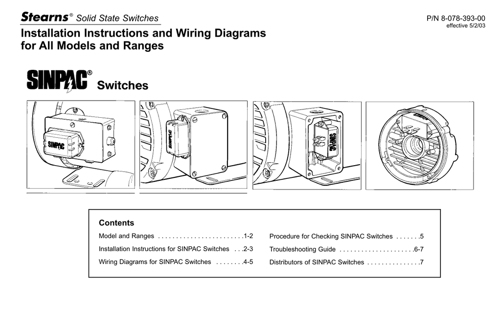
Stearns Sinpac Switch Wiring Diagram
Sinpac switch exposed to excessive temperature. Stearns brake wiring diagram eyelash me.

Sinpac Switch Wiring Diagram Free Wiring Diagram
Bodine electric n4698 right angle dc gearmotor 06 hp 24vdc 63 rpm.
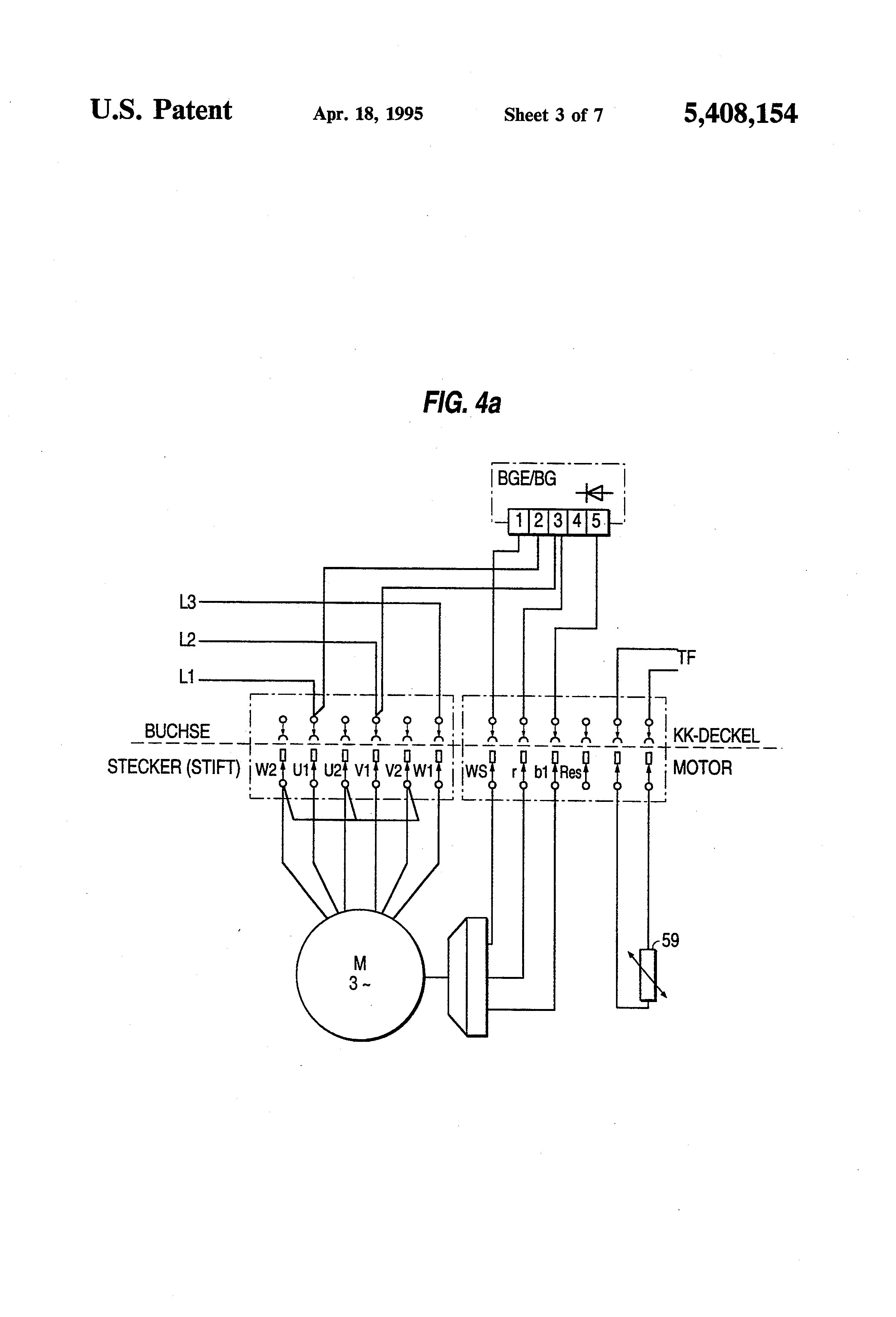
Stearns sinpac switch wiring diagram. 4 7 42050 05 stearns sinpac switch cvrcv. My problem is that elevator controls are very complicated to understand. Stearns direct comc inetpub stearns direct products solid state switches for single phase motors sinpac switches for capacitor start motors cv series 115v.
Leeson 5 hp brake motor 3 phase 1800 rpm 230 460 v 184tc frame tefc 132480 00 Replace sinpac switch after checking all of above possible causes. Be sure that terminal 4 of
472104011u03 stearns® sinpac® electronic switch. Stearns offers the most comprehensive line of solenoid actuated brakes (sab’s) on the market today. Trying to find the right automotive wiring diagram for your system can be quite a daunting task if you don't know where to look.
Prepare the motor wiring for connection of the sinpac switch as shown in the wiring diagrams for sinpac switches section of this publication. Diagram dc motor internal wiring diagram full version hd. Sinpac switches will operate in areas susceptible to brownouts or low voltage due to long wiring runs.
Stearns brake 1 048 161 00 bq nema 2 208 230 460 3 phase. Stearns brake wiring diagram eyelash me. This article will demonstrate how to wire a tog.
Bodine electric n4698 right angle dc gearmotor 06 hp 24vdc 63 rpm. Mechanical switches are prone to. Longer motor life starts with a switch.
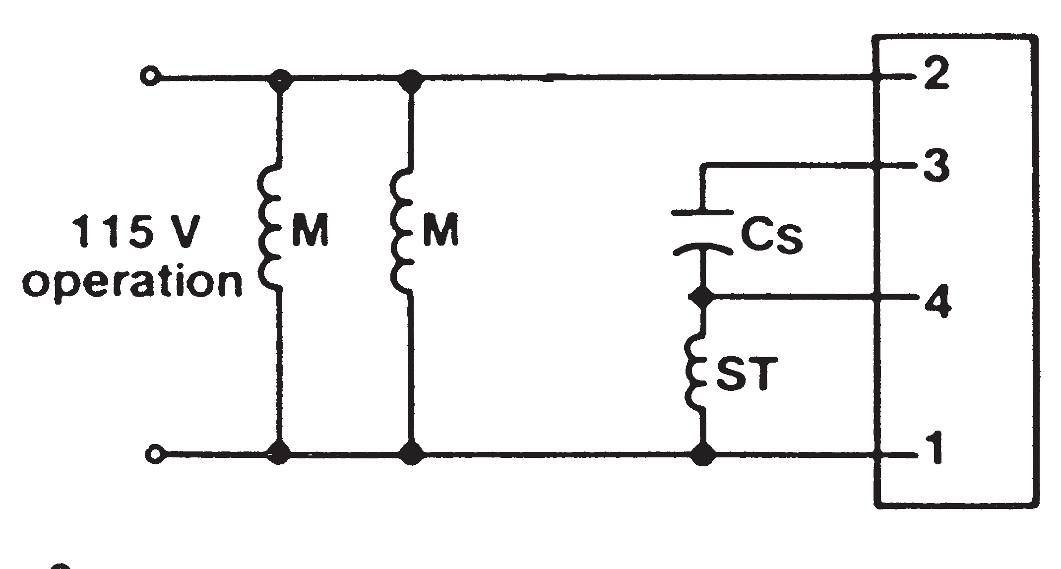
Sinpac instant reverse switch is not dependent upon how quickly the user operates the reversing switch, but only that the reversing switch did change states, i.e., forward to reverse, or vice versa. It should be less than 80°c (185°f). The sinpac switch detects the change in the phase shift between the main and start windings, and the logic circuit instantly actuates the starting switch, causing the start circuit to.
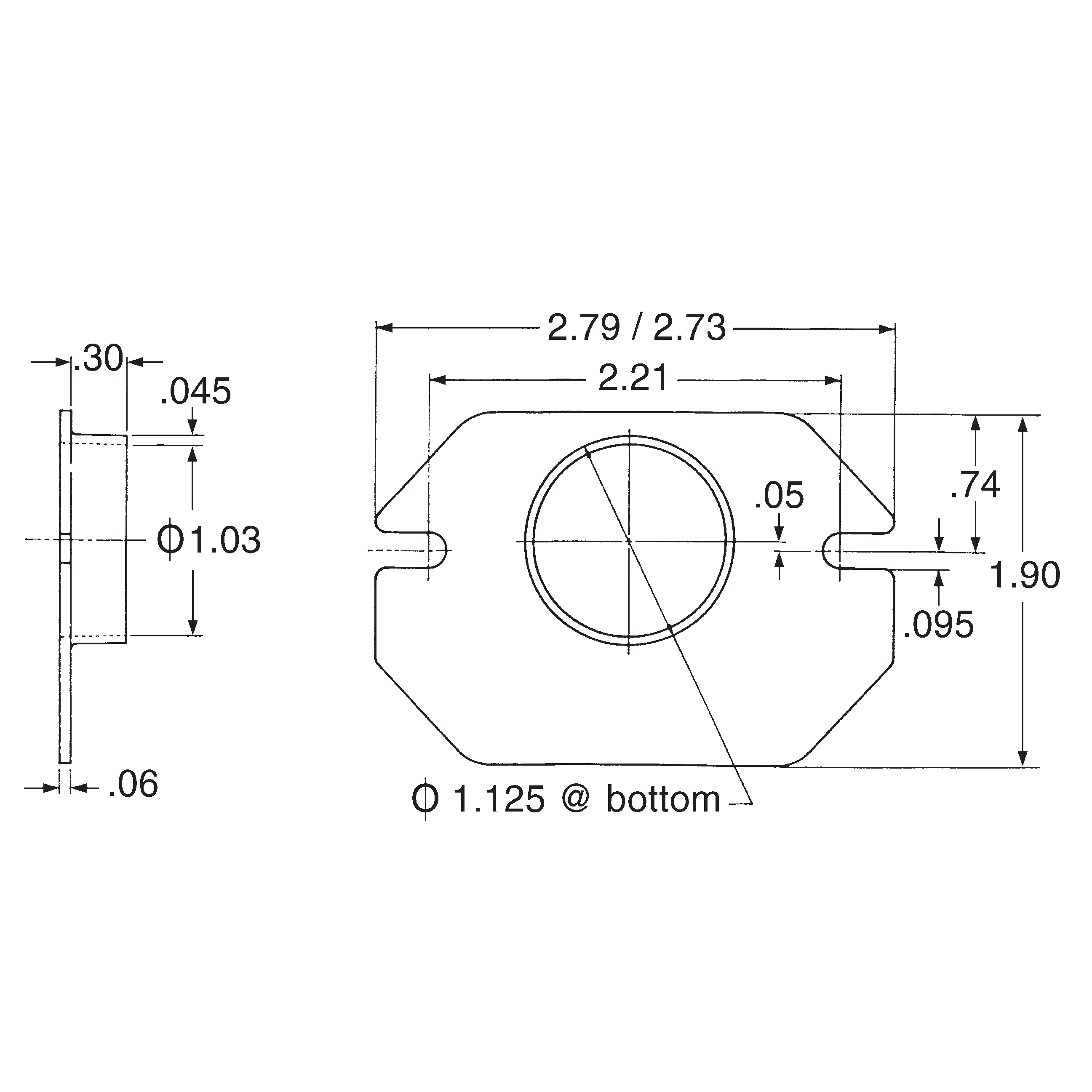
To help you with the installation and accuracy in wiring our programs, we’ve put a collection of wiring diagrams at your fingertips. Diagram dc motor internal wiring diagram full version hd. / products / stearns® sinpac® switches / cv / 2cv series / 472104011u03 stearns® sinpac® electronic switch.
Browse stearns technical support, general information, distributor locations, and more. New, 115vac 50/60hz, 25a max current. For capacitor start/run motors, 130 vac cut out, 40 amp.
Connect the lead wire that is to be connected to sinpac switch terminal #2 securely to the lead wire that is to be connected to sinpac switch terminal #3. See procedureto check sinpac switch (page 28). 472101611u03 stearns sinpac electronic start switch 115v 16a from www.witmermotorservice.com 3 way switch.
The motor has a 115 ir (insta reverse) switch but the motor is rated at 230 vac. When ordering a stearns sinpac electronic switch. The sinpac switch detects the change in the phase shift between the main and start windings, and the logic circuit instantly actuates the starting switch, causing the start circuit to.
Black, yellow, orange and white. Stearns brake 1 048 161 00 bq nema 2 208 230 460 3 phase. Secure the motor to a firm mounting surface.
The sinpac switch detects the change in the phase shift between the main and start windings, and the logic circuit instantly actuates the starting switch, causing the start circuit to. Leeson 5 hp brake motor 3 phase 1800 rpm 230 460 v 184tc frame tefc 132480 00 4 7 42050 05 stearns sinpac switch cvrcv.
Sinpac instant reverse switch is not dependent upon how quickly the user operates the reversing switch, but only that the reversing switch did change states, i.e., forward to reverse, or vice versa. 478104015ua3 stearns® sinpac® instant reversing switch. 1 056 000 series installation and service pdf manualslib table of contents direct comc inetpub products solid state switches single phase motors sinpac split 65 300 05 brakes rev c d e 56 143 5tc double face coupler 87 00 01 02.
There are 4 wires coming out of the motor. Sinpac instant reverse switch is not dependent upon how quickly the user operates the reversing switch, but only that the reversing switch did change states, i.e., forward to reverse, or vice versa.
Sinpac Switch Wiring Diagram General Wiring Diagram

30 Sinpac Switch Wiring Diagram Wiring Diagram List


Sinpac Switch Wiring Diagram Wiring Diagram

Sinpac Switch Wiring Diagram Wiring Diagram
Sinpac Switch Wiring Diagram General Wiring Diagram

Stearns Motor Brake Wiring Diagram Wiring Diagram
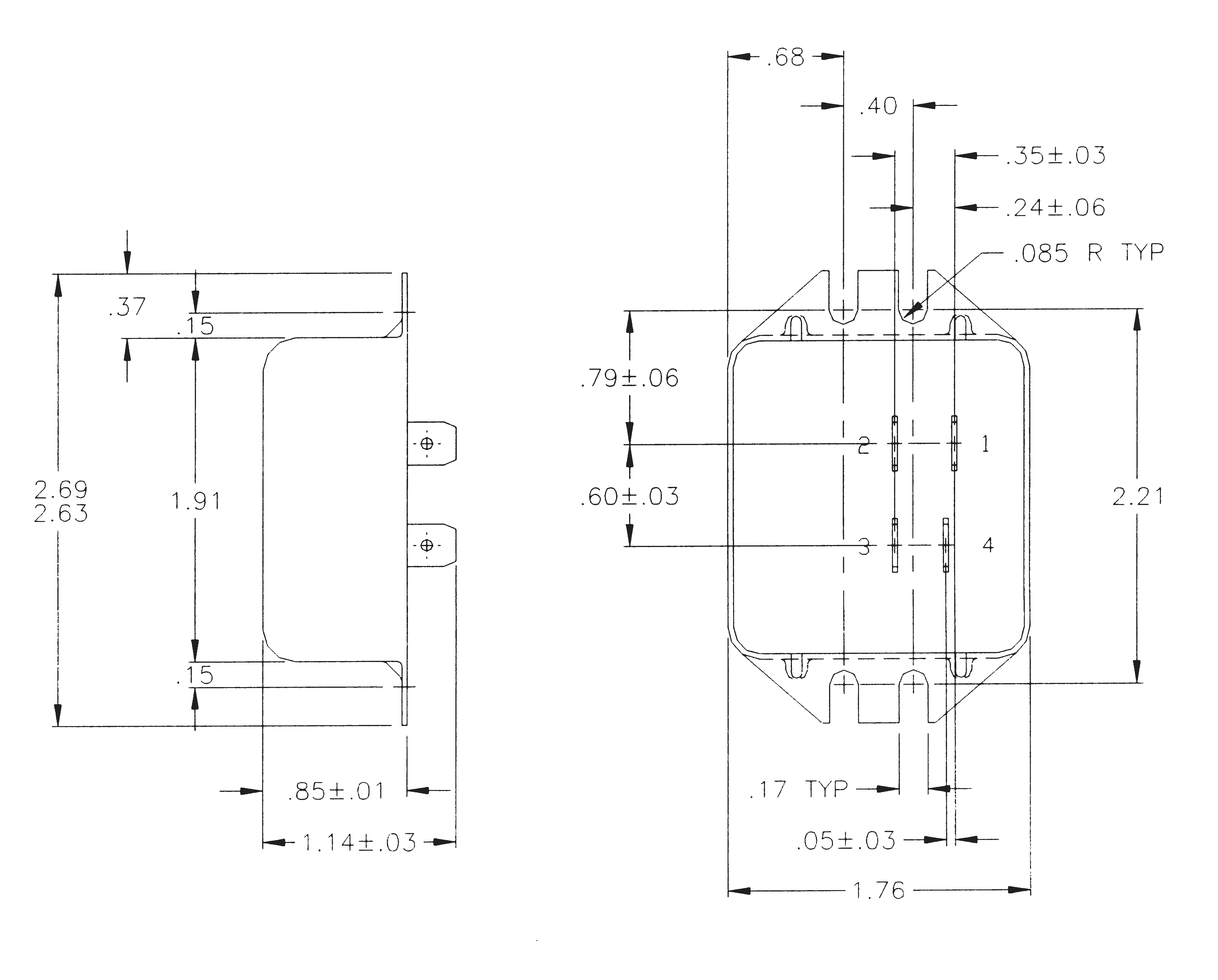
472101611U02 Stearns SINPAC® Switch, 115V, 16A,

475102515UA1 Stearns® SINPAC® Instant Reversing Switch

Sinpac Switch Wiring Diagram Free Wiring Diagram
18 Unique Sinpac Switch Wiring Diagram

Wiring Diagram 30 Sinpac Switch Wiring Diagram

18 Unique Sinpac Switch Wiring Diagram


Sinpac Switch Wiring Diagram General Wiring Diagram
Sinpac Switch Wiring Diagram Free Wiring Diagram

472104011U03 Stearns® SINPAC® Electronic Switch
Stearns Motor Brake Wiring Diagram Wiring Diagram
Sinpac Switch Wiring Diagram General Wiring Diagram
477104012U03 Stearns® SINPAC® Electronic Switch

27 Sinpac Switch Wiring Diagram Wiring Database 2020